
Thermal Flame Spraying Equipment Gun for Thermoplastic Powder
Introduction
PECOAT® PECT6188 is equipped with a unique wheeled stainless steel high capacity powder feeder that allows for simultaneous use of two spray guns. It features a whirlwind fluidized bed powder supply structure with an adjustable venturi powder absorber and a powder cleaner. The continuous addition of powder to the feeder ensures long-term, stable, and consistent operation of the spray gun. The specially designed air mixing mode and double-layer protection structure of the spray gun prevent any tempering during the spraying process. It enables fast application of EAA, EVA,PO, PE, epoxy as well as other thermoplastic and thermoset plastic powders. A single spray can create a coating thickness ranging from 0.5mm to 5mm.
The spray gun is designed for special gas mixing mode and double layer protective gas structure, and there will be no tempering in the spraying process. It can quickly spray ethylene-acrylic acid copolymer EAA, ethylene-vinyl acetate copolymer EVA, polyolefin PO, polyethylene PE, cross-linked polyethylene, epoxy powder, chlorinated polyether, nylon series, fluoropolymer powder and other thermoplastic powder and thermosetting plastic powder on-site construction. One spraying can form a coating of about 0.5-5mm, It is suitable for the construction of chemical installations, large containers, storage tanks, oil and gas pipelines and other on-site construction.
Equipment Composition
- High-power flame spray gun, powder feeder, regulating valve.
- Users are required to provide their own 0.9m3/min air compressor, oxygen, acetylene, oxyacetylene pressure reduction meter, and pipeline.
Features
The coating is thick, ensuring durability and protection. The operation is simple and user-friendly. The equipment is lightweight and portable, facilitating easy transportation.
Advantages include:
- low cost as there is no need for specialized spraying or drying rooms. Additionally, the equipment’s portability allows for on-site construction without limitations based on workpiece size or shape.
- It can be applied under various environmental conditions such as 100% relative humidity and low temperatures.
- Compatible with a wide range of matrix materials including steel, concrete, etc., allowing for versatile applications.
- The coating offers repairability; small defects can be easily fixed by heating the surface while larger defects can be re-sprayed entirely if needed.
- Powder and color changes are effortless to implement.
Application Examples
- Various corrosion-resistant containers for alcohol, beer, milk, salt, food, and sewage treatment equipment; thermal power plant steel desalination water tanks including ultrafiltration water tanks, primary fresh water tanks, secondary fresh water tanks, raw water tanks and other internal corrosion prevention measures.
- Diverse applications in steel structure anticorrosion, decoration, insulation, wear resistance and friction reduction: Petrochemical and power plant large storage tank and pipeline welding repair using two-layer PE or three-layer PE anti-corrosion coatings; highway guardrails; municipal lighting poles; stadium grid engineering; tap water pumps; chemical fans; printing machine nylon rollers; automobile spline shafts; electroplating hangers.
- Marine steel structures and port facilities such as bridge foundations, breakwaters, plate bridges, steel pipe piles,sheet piles,trestles,and buoys to prevent seawater corrosion.
Photos of Spraying Gun
 Wooden Package -Weight 25KG
 Thermal flamespraying machine gun
 Thermal flamespraying machine gun
 Accessories of flame spraying gun machine
 Powder feeder tube connection
 Flame spraying gun
 Flame spraying gun
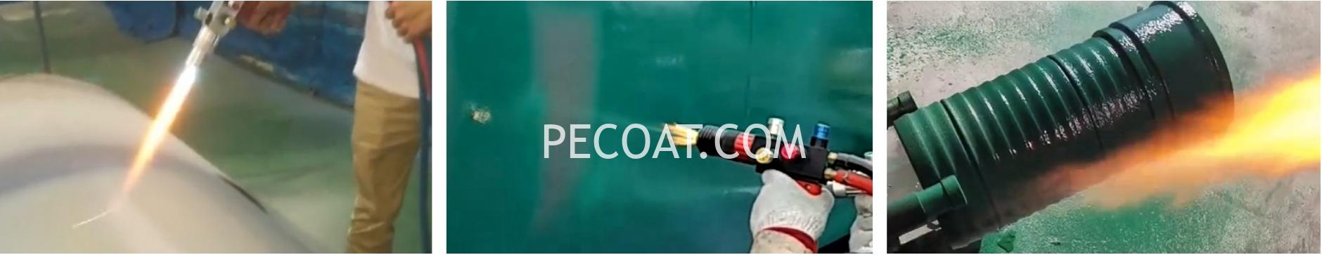
Flame Spraying Process
The flame spraying process primarily consists of substrate surface pretreatment, workpiece preheating, flame spraying, detection, and other procedural steps.
- Substrate surface pretreatment: Large components or containers can undergo processes such as sandblasting, polishing, pickling, or phosphating to eliminate surface oil, rust, or other corrosive substances. Research indicates that sandblasting and phosphating are the most effective methods for combining with flame spray coating.
- Preheating: The workpiece’s surface must be heated above the melting point of the plastic powder before application. This step is crucial and can be achieved using a flame spray gun. Different plastic powders and workpiece shapes/specifications require varying preheating temperatures. Detailed information on different plastic powders’ recommended workpiece preheating temperatures is provided in the following spray parameters.
- The flame power of the spray gun is determined by the gas pressure and flow rate, with high-power gas flames leading to combustion deterioration of plastic powder, while low-power gas flames result in poor coating adhesion and incomplete plasticization. The flame power mainly depends on the particle size of the plastic powder, where coarse powders require high-power flame spraying and fine powders necessitate low-power flame spraying.
- Spraying Distance: When using thermoplastic powder with a particle size of approximately 60-140 mesh, the recommended spraying distance is around 200-250mm. For thermosetting plastic powder with a particle size of about 100-180 mesh, it is advisable to maintain a spraying distance between 140-200mm.
- Compressed air, carbon dioxide, and nitrogen are commonly used as protective gases during spraying operations. Among them, carbon dioxide provides superior cooling effects while nitrogen is suitable for nylon material spraying protection. Coarse powders require slightly lower protection airflow compared to fine powders. The recommended pressure for the protective gas ranges from 0.2 to 0.4MPa.
- Generally speaking, the powder feeding amount for flame-sprayed plastics falls within the range of 60 to 300g/min. If a coating thickness greater than 0.3mm is desired without any pores present in the coating surface, this feeding amount should be maintained accordingly.
- According to different types of plastics being used, when applying a powder spraying amount of 300g/min and aiming for a film thickness of 1mm per hour using one spray gun can achieve an efficiency ranging from12 to15m²/hour.
- Detection methods should be selected reasonably based on film thickness requirements; typically employing thickness gauges or EDM leak detectors.
Preparatory Work
- Air compressor: The air compressor should have a displacement of at least 0.9m3/min and a working pressure ranging from 0.5 to 1Mpa. It should deliver dry and clean compressed air into the spraying equipment after passing through an oil and water filter.
- Spray gun and powder feeder pipeline connection: Firmly connect a high-pressure hose with an inner diameter of φ15mm to the total air inlet connector of the powder feeder. Then, connect the left and right air ball valve joints at the air pressure gauge seat of the powder feeder to the spray gun handle using a high-pressure hose with an inner diameter of φ10mm. Also, firmly connect the lower left protective gas connector (one for each spray gun). Connect transparent plastic hoses with an inner diameter of φ12mm respectively to both left and right powder feeding joints, as well as to the lower right powder feeding joint on each spray gun handle (each group has one spray gun). The powder feeder is designed for simultaneous spraying by two spray guns. If only one spray gun is used, either the left or right group’s compressed air and powder feed joint can be closed separately.
- Spray gun and oxygen/acetylene gas pipeline connection: Directly connect acetylene gas hose to the left upper acetylene gas connector behind the spray gun handle, followed by directly connecting oxygen hose to the right upper oxygen connector behind it.
- Spraying operation: Start running the air compressor for 3-5 minutes until reaching an air pressure gauge reading ≥5MPa on the powder feeder unit. Unscrew large plugs located on both upper cover and lower part of its barrel in counterclockwise direction; open reverse blow valve in counterclockwise direction to remove any remaining powders from feed barrel/pipeline; close reverse blow valve in clockwise direction; finally plug back large screws removed earlier.
Equipment Videos
